The purpose of this tutorial is to share with you our experience in assembling of the Magnorail system.
Please note, since this tutorial was written, may be the Magnorail product line has evolved. May be some products are no longer available or have evolved and that basic techniques have been improved by the manufacturer.
Our written tutorial can be difficult to understand. The photos are intended to help you understand how to complete the project.
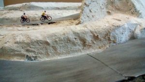
The club has decided to install a Magnorail animation on its new HOm layout under construction. This system makes it possible to create an animation of a cyclist (or any other rolling vehicle regardless of its size) moving on a road or a path. It can be used on any scale from Z to HO. For larger scales it is not certain that the magnets are strong enough to drive heavier vehicles. The most spectacular is the staging of the bikes on which the cyclist actually pedals. The result is quite nice.
There are a lot of videos on YouTube that show magnificent achievements based on the Magnorail system. Here are the links that allow you to admire one of the most interesting achievements (in our opinion):
(Be sure to view the two videos in order otherwise there is no longer any mystery).
1 – https://www.youtube.com/watch?v=ClEqYktvcOM
2 – https://www.youtube.com/watch?v=ivhFLcfcCv8
Components and parts used
The choice of the theme and the model that we wished to build led us to buy a BF-1 starter Kit. The length of runway contained in the kit (225 cm) being insufficient to implement our project, we therefore bought 2 UE-1 extensions of 60 cm. The chain length to be trained on the 340 cm track with several vehicles or bikes led us, on the effective advice of the vendor, to buy a second speed drive module identical to the one in the BF-1 starter Kit.
Content of the kit
The explanatory note is only based on sketches. No text to explain the method. When we lacked information or clarifications, the vendor kindly gave us when we asked for them. This information is given in this tutorial when it can be useful to know.
Parts for which we did not find the use or installation method:
– The various chain elements are identified on the sketches and on the clusters with the letters S, T, R, Q and X. On the instructions, there are sketches which specify how to use the elements R, Q and X. on the other hand no info or sketches on the specific installation of S and T elements.
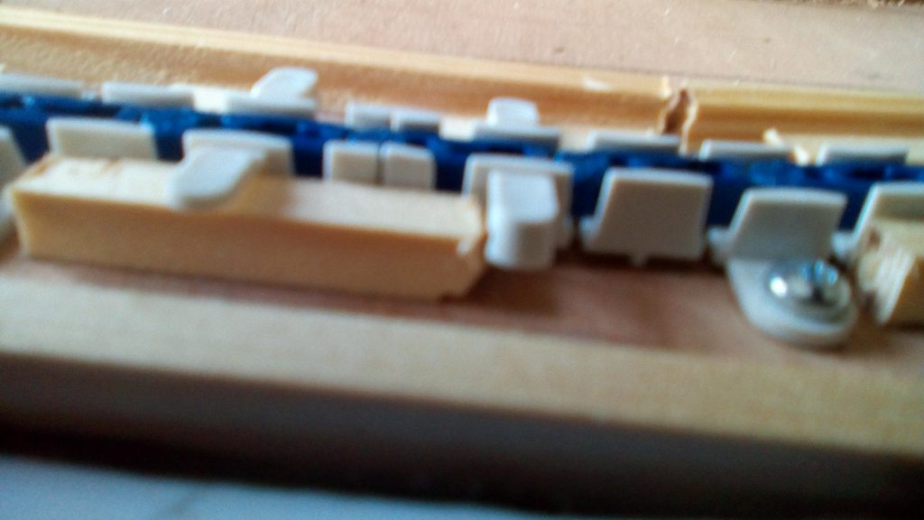
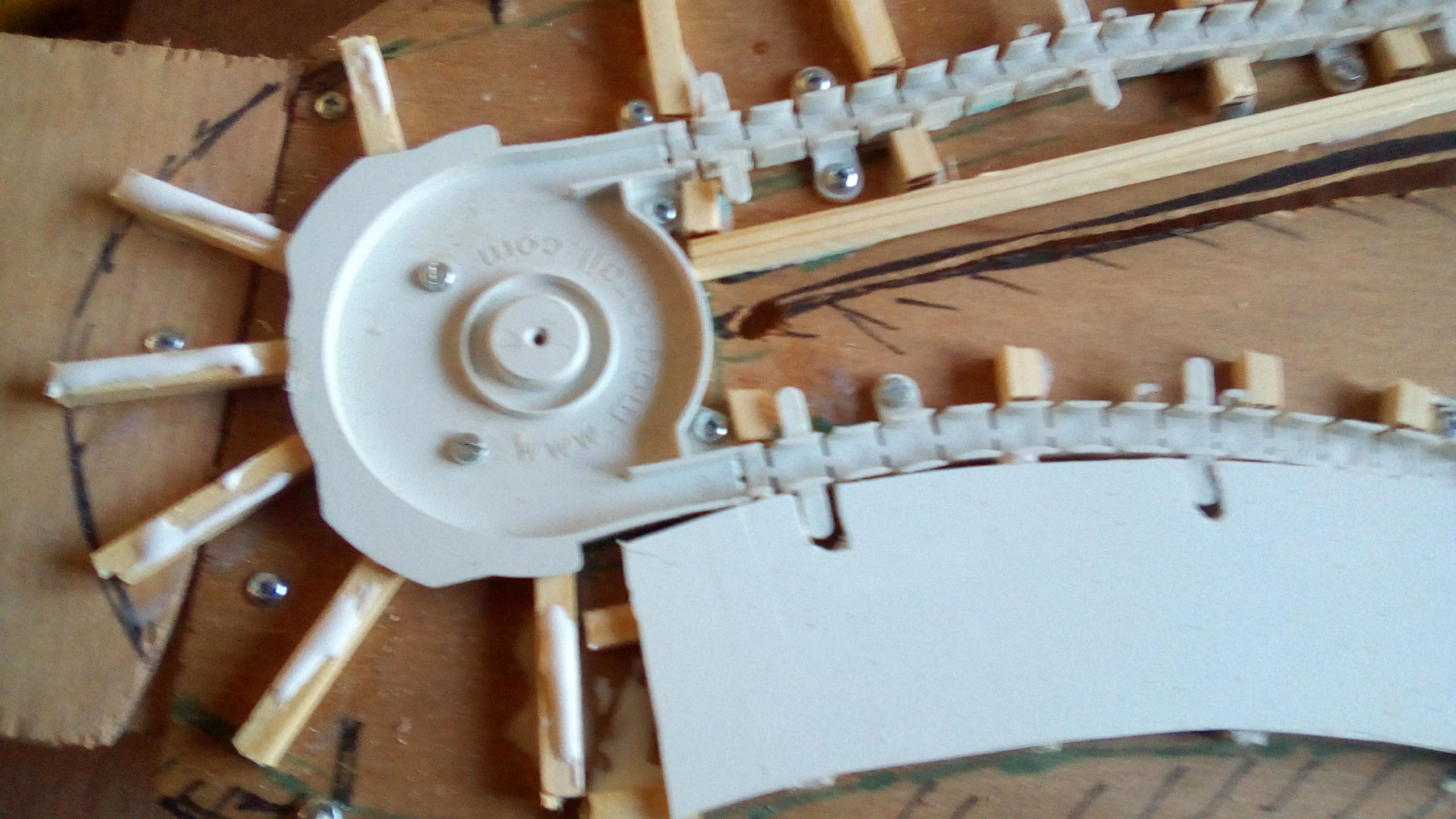
– There are side lugs on the guide rail elements. We have not found what they are used for. (view the photo)
– On the elements of the guide rails, there are the supports on which the road will have to be fixed. Some of these supports have an outgrowth underneath. We have not found their usefulness (and use). (view the photo)
– There is in the kit a bag of domed wood screws to fix the rails on the support plate. There are countersunk screws in the same bag which look not like wood screws and for which we have not been able to find the use.
Mounting the flexible guide rail
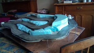
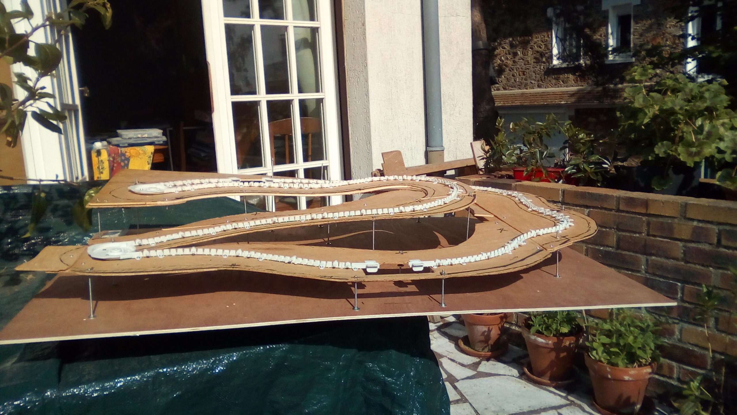
The road we wanted to build presents differences in level. The high point being 12 cm above the low point. If you want to create a circuit with height differences, it is advisable to make a light sketch by marking the planned height differences. This will be necessary to size some parts later.
– The first step was to create a provisional flat road. This made it possible to verify that, in this configuration, the motors were correctly driving the chain.
– Second step: fixing the track, flat, on a 3 mm plywood. For practical reasons, we have chosen to replace the screws supplied in the box with 3 × 12 steel bolts. To ensure fastening without worrying about loosening over time, we used nylstop (self-locking) nuts.
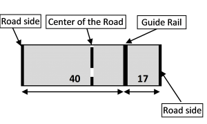
– Third step: draw the road on the plywood. We have chosen a width of 17 mm from the centre line of the runway on the right in the direction of travel and 40 mm on the left (this part represents the opposite taxiway). Depending on the type of road or lane represented, everyone is obviously free to choose the widths they want. Reverse the hereunder sketch for left-hand traffic.
– Fourth step: Cutting the edges of the road to allow the formation of the relief.
It will be necessary to cut some edges of the road to allow the “unfolding” in height of the plywood. To identify the saw cuts to be made, proceed as follows: Imagine that your road goes up in laces. After the switchback, the uphill road overlooks the road before the switchback. You will have to cut the plywood 1 or 2 cm from the limit of the “upper” road. The sketch you have made speaks better than long speeches. During the following operations, it will always be possible to extend the saw cuts. if necessary, to ensure better “unfolding”.
The 3 mm plywood, on which the flexible guide rails are fixed, must now be positioned on the support of the assembly which will also ensure the rigidity of the construction. Provide a plywood at least the same dimensions as the plywood to which the flexible guide rails are fixed and 5 or 8 mm thick.
The 3 mm plywood will be connected to the 5 mm support plywood with threaded rods of 3 or 4 mm diameter. Now is the time to drill the holes through which the threaded rods will pass. This allows the aligned holes to be drilled although, after unfolding, small adjustments may be useful. The holes must be drilled on the “precipice” side of the road and 2 cm from the saw cuts. Do not hesitate to make more holes than necessary, it is better to have more than not enough. It is more difficult to drill opposite each other on the two plywood sheets when the upper plywood is unfolded.

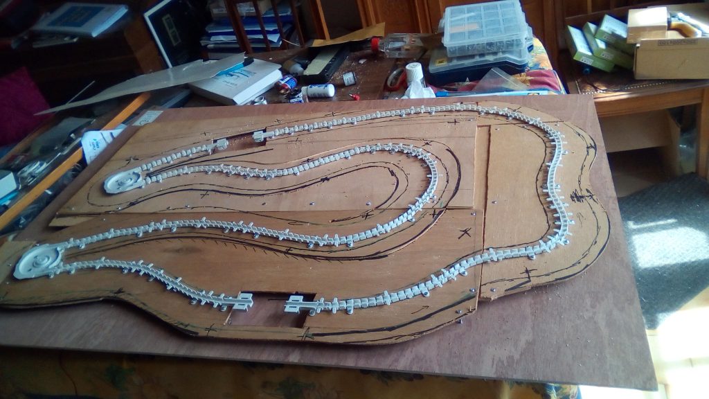
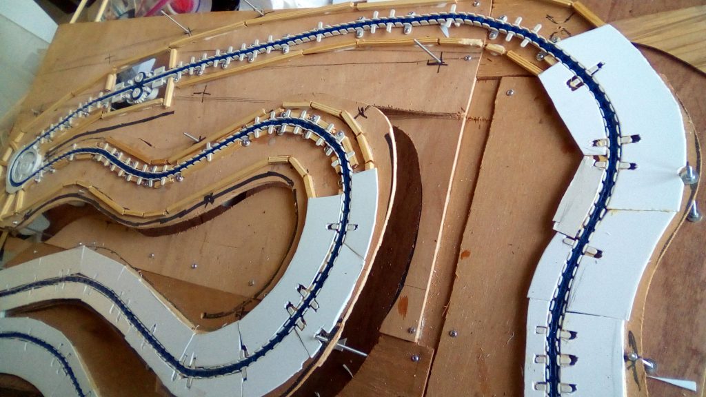
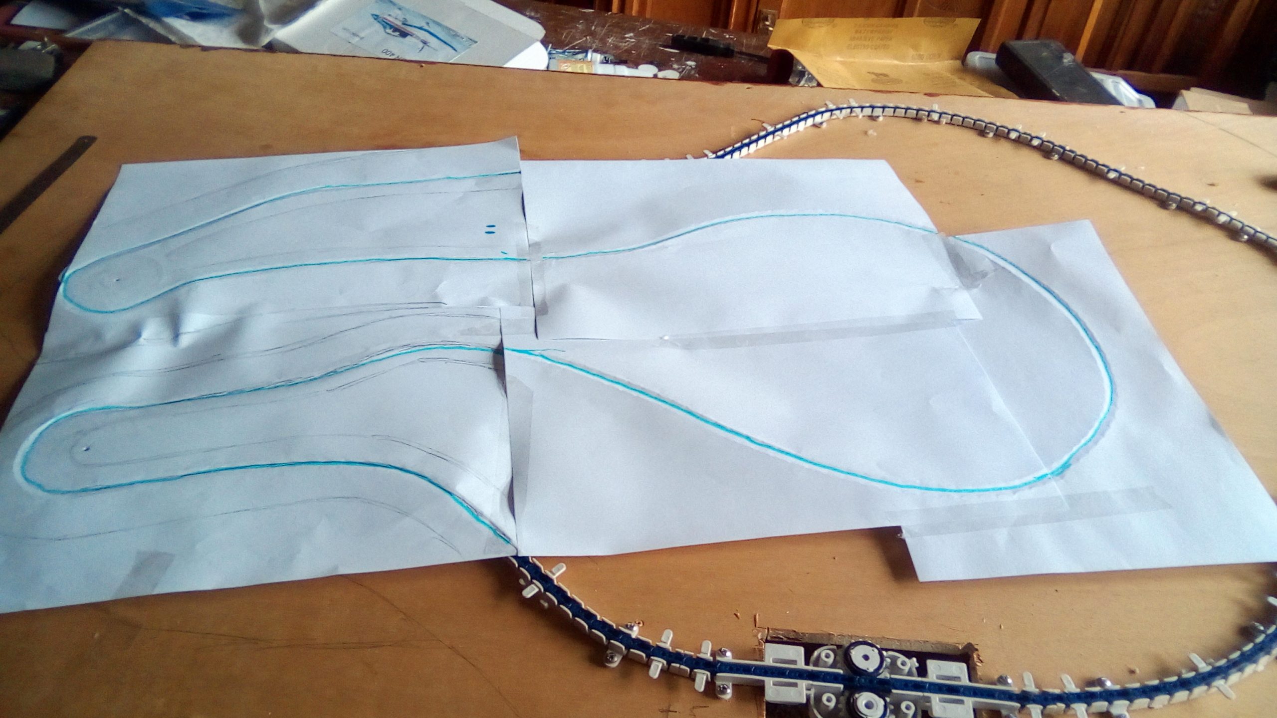
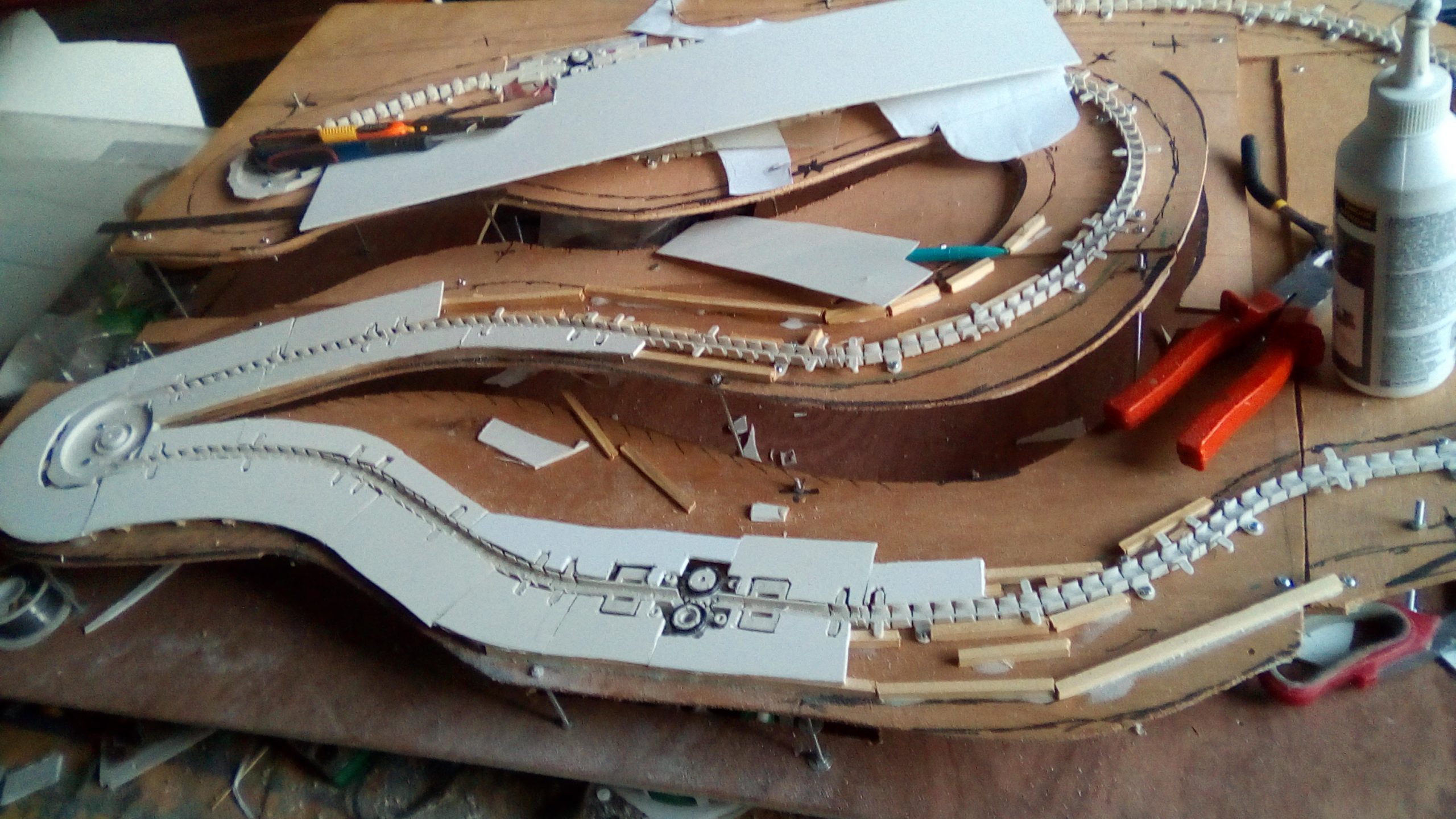
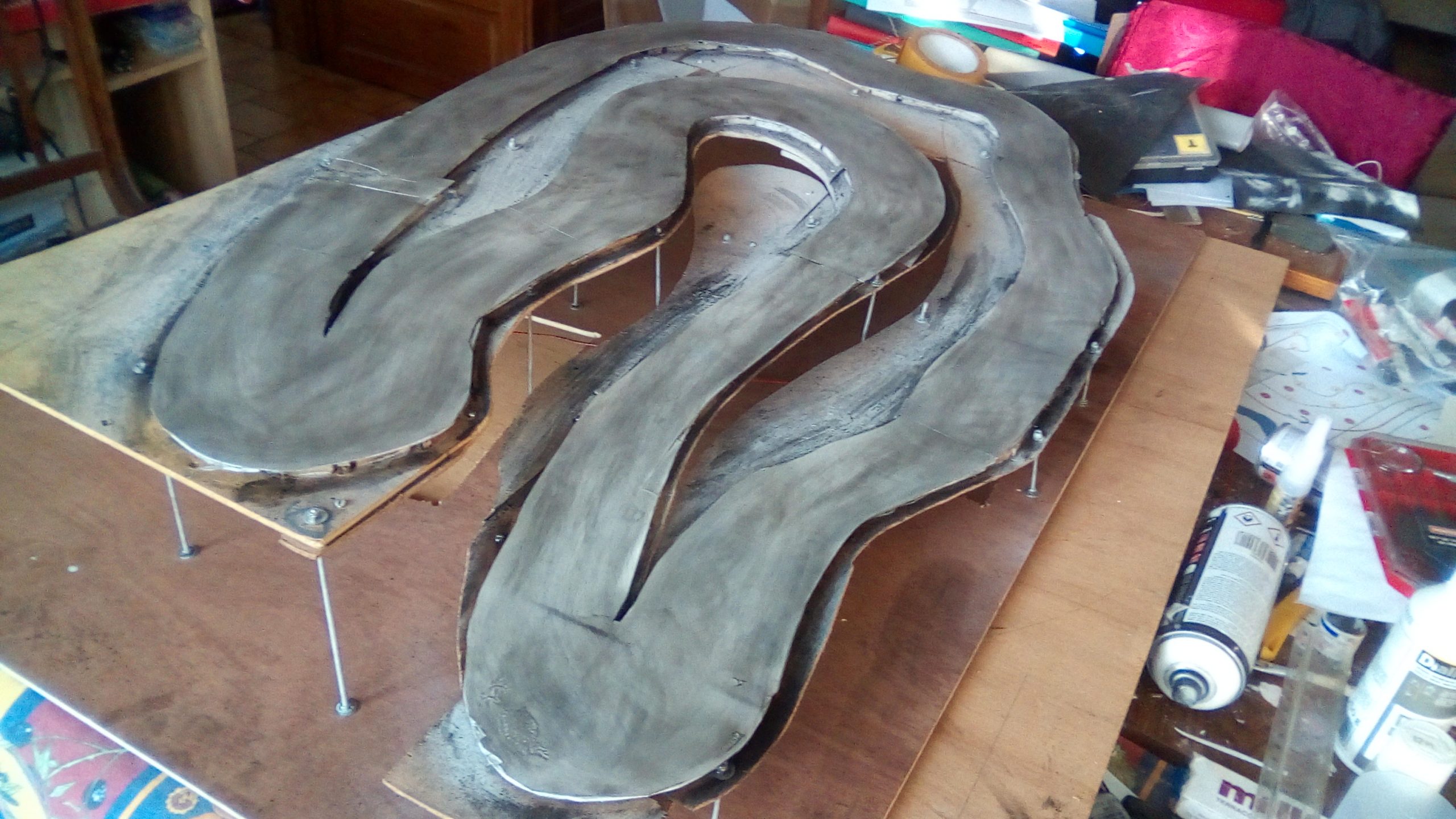
Photo A: Flexible guide rails mounted but not fixed for drawing the template on paper in order to transfer it to the plywood serving as a base for the road and which will allow it to be cut.
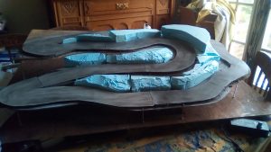
Photo B: After cutting the base, installation of Magnorail guide rail elements.
Installation of threaded rods
Cut the threaded rods to the necessary lengths. Do not hesitate to cut too long, it will always be possible to cut them to the right length once the whole is finished.
To fix the threaded rods to the plywood plates, it is imperative to use nylstop nuts + metal washers which will ensure better support on the plywood and prevent the wood from being crushed. Otherwise, it is possible to use standard nuts with metal washer + lock washer. It is important to secure the tightening with a nylstop nut or a lock washer because with use, vibrations of all origins favour the loosening of the nuts and therefore risk weakening the rigidity of the assembly.
To install the threaded rods, to each his own method.
Our method: we start by screwing two nuts which will tighten the upper part of the low plate and the lower part of the high plate. The rod is then inserted into the holes provided, the two nuts between the two plates (do not forget the washer between the plate and the nut). Do the same for all threaded rods.
Tightening the threaded rods on the lower plywood plate.
We will do this step for each threaded rod, rod after rod. We insert a washer in the lower part of the rod (face below the lower plate), then screw a nylstop nut. The rod must be flush with the nut (to avoid excess thickness or to cling to it) but it does not have to be. Then screw the “low” nut which is between the two plates and tighten completely. This tightening must be final.
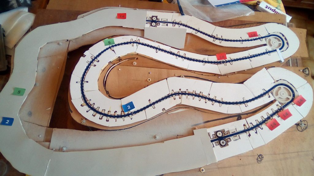
When all the threaded rods are fixed definitively on the “lower” plate, it is time to proceed with the unfolding and the formation of the relief. Start by positioning the road at the lowest level by sliding the “upper” plate on the threaded rod (s) to the correct height. Little by little it will be necessary to slide, on all the threaded rods, the upper plate upwards, otherwise unfolding will be mechanically difficult.
When the upper plate is positioned at the correct height in relation to the bottom plate (which is the reference height 0), stop the upper plate by tightening the two nuts on either side of the plywood. Do not forget before screwing the upper nut to insert a metal washer.
Be careful to fix the road horizontally in the direction of its width. It is possible to make a slight cant in tight bends.
After all this work, a little rest and we start building the road.
Construction of the roadway.
Note: At each important step, we have checked that the vehicles are correctly driven and that the chain slides perfectly.
After several tests, we adopted the following method:
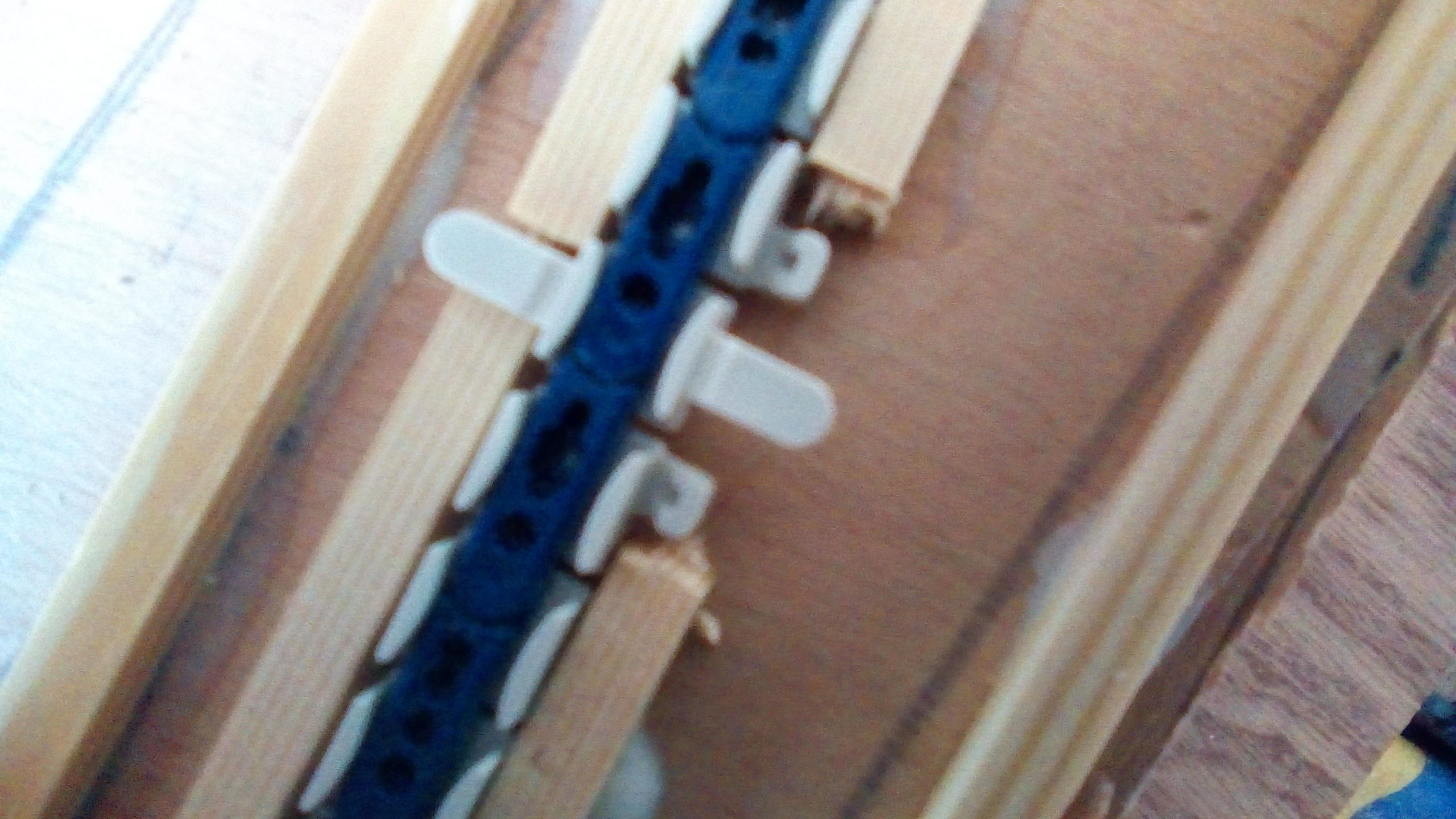
The “supports” of the road, moulded on the guide rails, have a height of 8 mm. The underside of the plate which will represent the road will therefore be 8 mm above the plywood on which the flexible guide rails will be fixed. To block and secure the positioning of the guide rails, as in the instructions, we immobilized them with 6×6 mm wooden sticks cut to the right dimensions (no need to cut the strips to the exact length required, they just need to be fit well against the rail). They are glued with wood glue.
We glue other identical strips that delimit the outer edges of the road (at a minimum). The marks of these borders were made in step 3 of point 2 at the beginning of this tutorial.
We install the pavement structure on either side of the guide rail with Forex 2 mm thick (miracle, added to the 6 mm of the rod, we arrive exactly at the 8 mm of the moulded support with the guide rail.). However, it is necessary to hollow out the Forex elements to make room for the protuberances that exist on the outer faces of the guide rails. Using Forex is convenient because it cuts easily and does not shatter like Plexiglas or other hard plastics. The Forex is glued to the rods with neoprene glue.

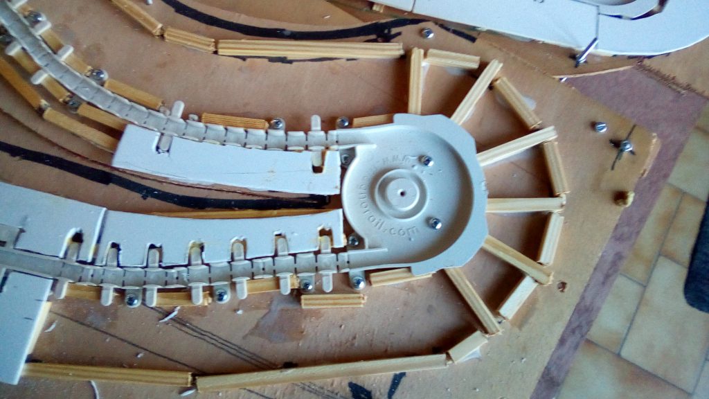
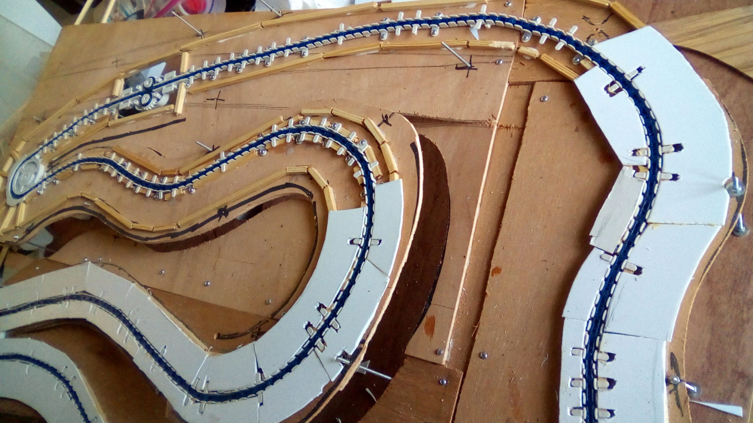
Photos below: different stages of the installation of the rails and positioning of the wood rods.

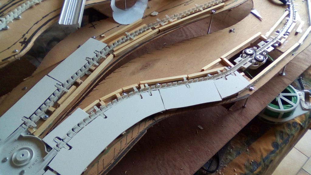

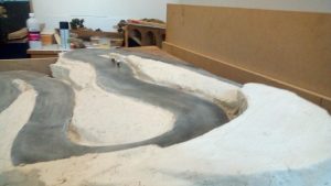
The road surface is cut from 0.5 mm PVC sheets. As this network is intended to be presented at exhibitions, the PVC sheets seemed to us to be more resistant over time than the cardboard sheets recommended by the instructions.
The PVC sheets cut to the right dimensions are glued with neoprene on the forex, being careful not to put glue on the rail and the chain. The continuity of the different coating elements does not pose a major problem to achieve. The chain slides smoothly nor jamming on the coating. After numerous operating tests, the result is satisfactory, the vehicles and bicycles can circulate without problem.
Laying the roadway above the drive motors.

As it is always good to foresee the case where the chain would jam and would need a manual push to be released (this happened to us without our having understood the why of the blockage), the pavement of the road above the engines and drive cogwheels was made on the principle of a removable cover and fixed by small very discreet screws.

Positioning and fixing the magnets
This step can be difficult if you don’t have a good method. The magnets are (very) small and ready to leap towards any metal mass nearby. The chance of finding again them is poor. To secure their handling, we select the magnet that we want to glue and make it adhere to the blade of a cutter. On the face of it, it will not escape, but you must still avoid placing another metal mass on which the magnet might want to jump …
Position and glue the magnets onto the links of the chain
If, following the instructions of the manufacturer, it is the “North Pole” of the magnet that must be positioned on the upper part of the chain link, the magnet must be positioned on the cutter blade so that the red compass needle is pushed back by the magnet. This means that the face of the magnet in contact with the cutter blade is the “North Pole”. It is then enough, while keeping the magnet glued to the blade of the cutter to present it above the hole of the chain link provided to receive it and to press on the blade at the level where the magnet is located to push it into his accommodation. It is necessary to slide the blade delicately to remove the cutter, it is then possible to release the blade, the magnet remains in its place.
If, following the instructions of the manufacturer, it is the “South Pole” of the magnet that must be positioned on the upper part of the chain link, the magnet must be positioned on the cutter blade so that the red compass needle is attracted by the magnet. This means that the face of the magnet in contact with the cutter blade is the “South Pole”. It is then enough, while keeping the magnet glued to the blade of the cutter to present it above the hole of the chain link provided to receive it and to press on the blade at the level where the magnet is located to push it into his accommodation. It is necessary to slide the blade delicately to remove the cutter, it is then possible to release the blade, the magnet remains in its place.
To secure the magnets in their holes, a small drop of cyano fixes the magnets permanently. Be careful not to put glue on the joints of the chain links
Stick the magnets on the sliders
The chain links, which are already equipped with magnets according to the slide assigned to them, serve as the support part
We place the slider on the chain links and present the micro-magnet stuck to the cutter blade. If it is presented in the correct direction, it will “jump” into the slider’s hole in the correct magnetic position. Just gently release the cutter blade by sliding it and possibly stopping the magnet with your finger or a non-metallic tip.(be careful not to overflow, which would risk sticking together the chain links and cursor together). Repeat the operation for all the magnets to be installed on the sliders
If you are assembling a “bicycle” kit, this operation is easier when the bicycle is flat, i.e. before bending the magnet supports at 90 °.
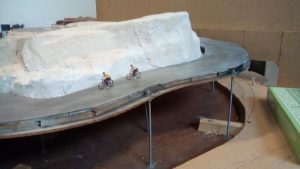
And there you have it, if all went well, your Magnorail is working wonderfully.
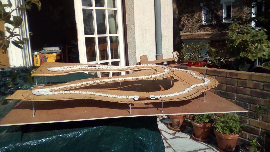
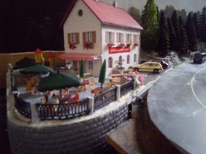
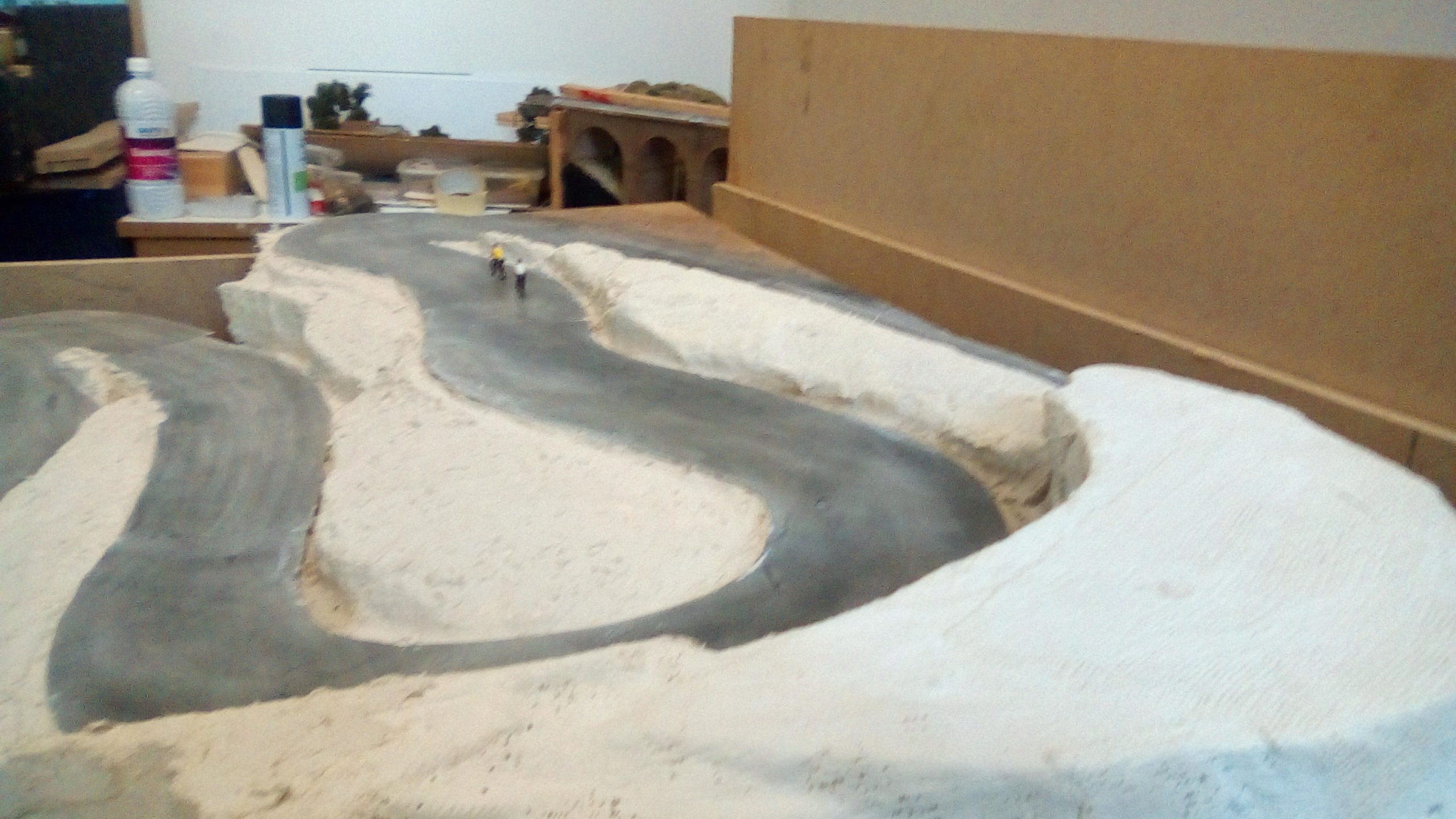
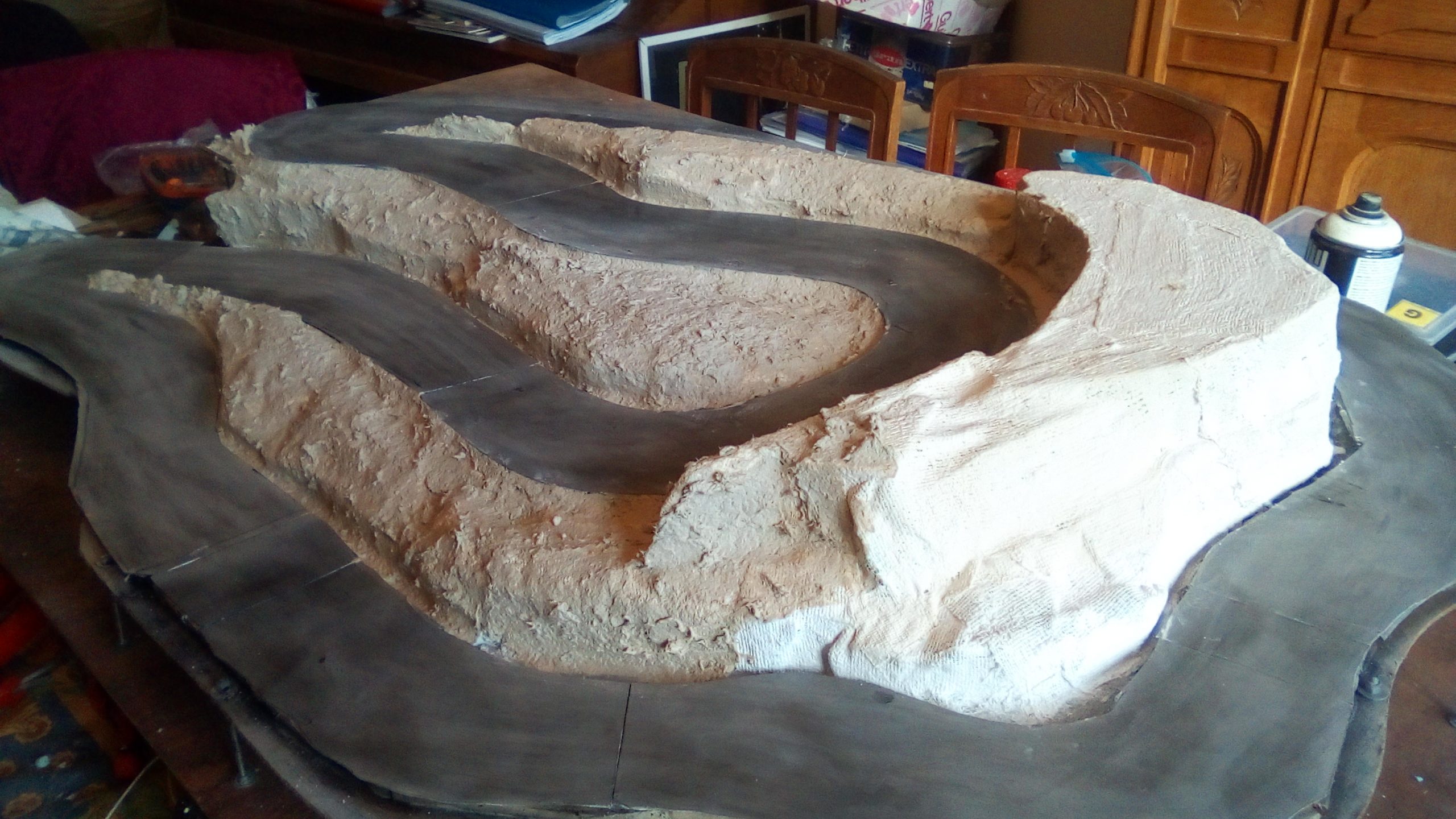
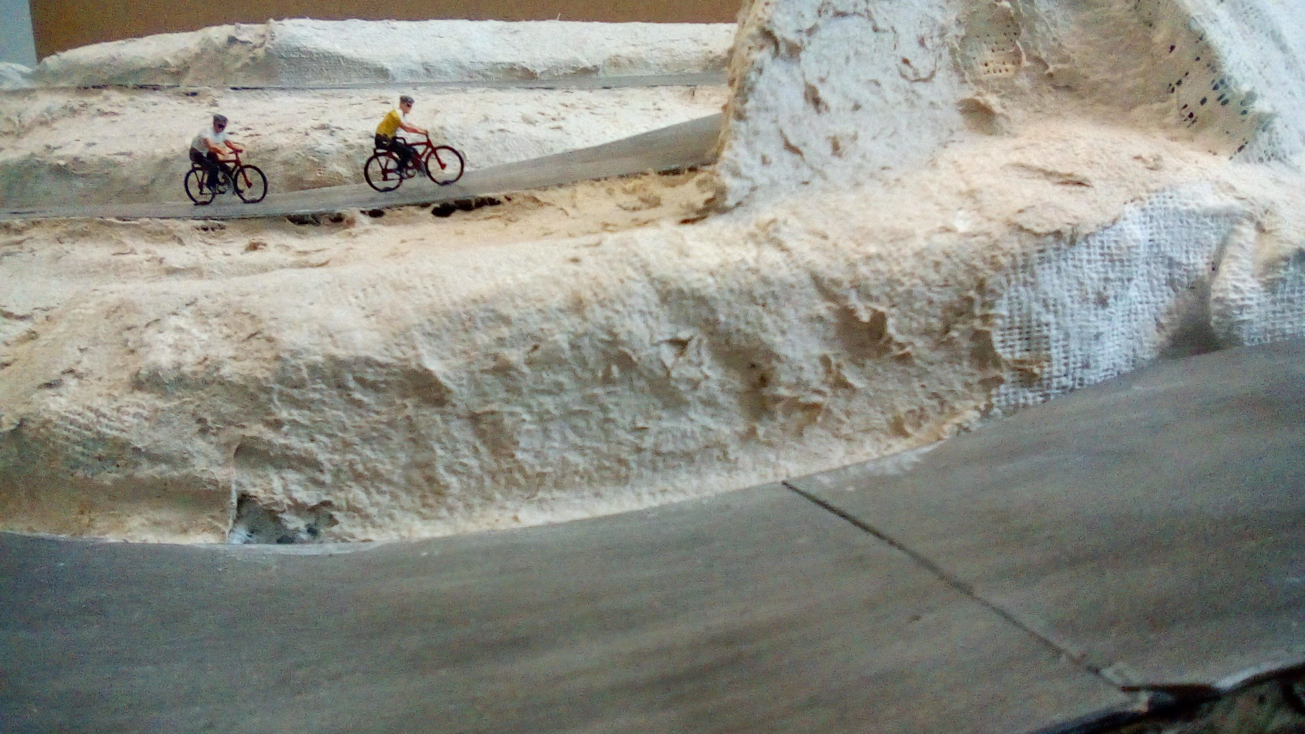
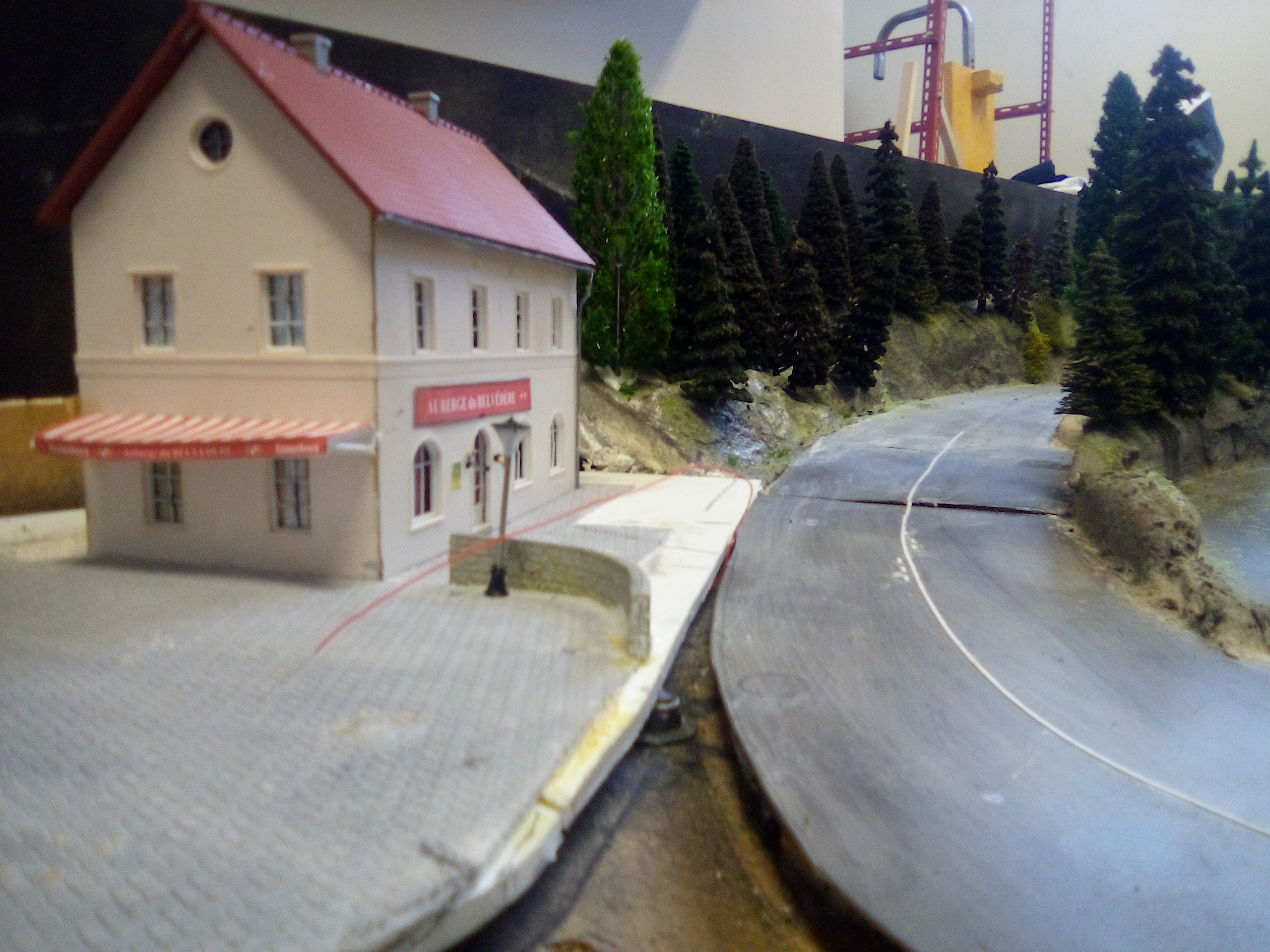
Below are photos of the current situation. The module is still under construction.


We have written this tutorial with many details at the request of less experienced modellers. If you have any suggestions for improvements, as with all of our tutorials, don’t hesitate to submit them to us, we will update the document if necessary.
We wish you lots of fun building and playing with your Magnorail system.
3 Comments. Leave new
Hi I would like to bay this system please send me more details were cen I buy this thanks
I don’t understand how you get the PVC cover sheets to go over the ‘hills’ without causing a separation line on the surface.
Aren’t they too rigid to bend this way?
Or do you use one huge sheet that is flexible enough to cover the entire area?
And if so, how do I find one?
Thanks
Hi,
I don’t quite understand your question. PVC sheets are used to make road surfaces. The road profile is generally horizontal or with small slopes. There is no difficulty in bending (not folding) PVC sheets of 0.25 mm or 0.50 mm thickness. The sheets are glued to the base of the road (see photos in the blog) and follow the profile of the road perfectly. There are no operating problems for both automobiles and bicycles. If I have not clearly understood your question and if I have not given you a satisfactory answer, feel free to ask me more to clarify your request.
The sheets we use are 600mmx300mm Evergreen Styrene Sheets. The most used references are EV19010 (Thickness 0.25mm), EV19015 (Thickness 0.38mm), EV19020 (Thickness 0.50mm).
We buy them in France from a seller in Strasbourg.
Best regards
Hello,
Je ne comprends pas très bien votre question. Les feuilles de PVC sont utilisées pour faire le revêtement de la route. Le profil de la route est généralement horizontal ou avec de petites pentes. Il n’y a aucune difficulté pour courber (pas plier) les feuilles de PVC de 0.25 mm ou 0.50 mm d’épaisseur. Les feuilles sont collées sur la base de la route (voir photos dans le blog) et suivent parfaitement le profil de la route. Il n’y a aucun problème de fonctionnement aussi bien pour des automobiles que pour des vélos. Si je n’ai pas bien compris votre question et si je ne vous ai pas apporté de réponse satisfaisante, n’hésitez pas à préciser votre demande.
Les feuilles que nous utilisons sont des plaques de styrène Evergreen de 600mmx300mm. Les références les plus utilisées sont EV19010 (Epaisseur 0.25mm), EV19015 (Epaisseur 0.38mm), EV19020 (Epaisseur 0.50mm).
Nous les achetons en France chez un vendeur à Strasbourg.
Cordialement